Have any questions?
Get in touch-
Tel : +86 18355532477
-
Whatsapp : +8618355532477
-
Email : 247137166@qq.com
-
Skype : 247137166@qq.com
- contact


Have any questions?
Get in touchTel : +86 18355532477
Whatsapp : +8618355532477
Email : 247137166@qq.com
Skype : 247137166@qq.com
Microstructure and Wear Resistance of Ni-Based WC Coating by Ultra-High Speed Laser Cladding
May 08 , 2021Abstract:
Steel materials are highly sourced construction materials owing to their robust mechanical properties, and they are widely used in the construction industry for building bridges, tunnels, skyscrapers, towers, ship-metal parts, and other industrial metal applications. However, as steel has poor surface wear resistance, parts are susceptible to failure due to friction damage. To improve the surface wear resistance of steel materials, Ni-based WC coating was prepared by ultra-high-speed laser cladding. Using low-speed laser cladding as a reference, the surface morphology, microstructure, and wear resistance of ultra-high-speed laser cladding of Ni-based WC coatings were studied using SEM, EDS, and XRD, respectively. Experimental results revealed that the Ni-based WC coating prepared by ultra-high-speed laser cladding exhibited better surface quality compared with that prepared by low-speed laser cladding. Comparatively, ultra-high-speed laser cladding requires a smaller heat input and a faster cooling rate. However, the dilution rate of the coating is significantly reduced. In addition, ultra-high-speed laser cladding significantly reduces thermal damage in the WC coating; it inhibits the precipitation of carbides and formation of porosities and promotes the uniform distribution of the WC in the coating, thereby significantly reducing stress localization in the coating and also inhibits crack nucleation in the coating. Because of the reduction of porosities, cracks, and other surface defects in the coating and uniform distribution of WC particles, the Ni-based WC coating prepared by ultra-high-speed laser cladding possesses better wear resistance than that prepared by low-speed laser cladding, and the wear mechanism is abrasion.
Experimental Method:
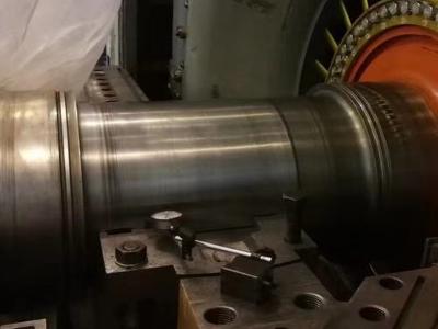
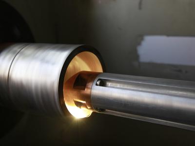
The base material used in the experiment was a 45 steel pipe with a diameter of 60 mm, a length of 300 mm, and a wall thickness of 6 mm, which was polished with sandpaper and cleaned with alcohol before cladding. The cladding material is Hegenas LC-WC-60 powder with a particle size of 50-150 μm, and the WC content is 30% (mass fraction). Before cladding, place the powder in a drying oven at a temperature of 120 ℃ for 30 min.
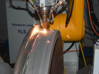
An MFM-6000W multimode continuous fiber laser with a maximum output of 6 kW and a self-designed ultra-high-speed laser cladding ring-shaped coaxial powder feeder (powder utilization efficiency can exceed 85%) are used to carry out ultra-high-speed laser cladding experiments. The RFL-A2500D laser with a maximum output power of 2.5 kW was used to carry out low-speed laser cladding experiments. The laser spot output is a circular spot with a diameter of 2 mm, and both the powder feeding gas and the protective gas adopt Ar gas (purity>99.9%).
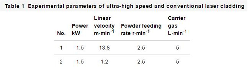
According to the preliminary process experiments results, to obtain excellent quality cladding coatings, the ultra-high-speed laser cladding linear velocity is set to 13.6 m/min, the laser power is set to 1.5 kW, and the powder feeding rate is set to 2.5 r/min. Low-speed laser cladding generally uses a linear velocity of 0.3~1.8 m/min. In this study, the linear velocity is set to 1.2 m/min, and other process parameters are consistent with ultra-high-speed laser cladding. The specific experimental parameters are shown in Table 1, where No.1 is the ultra-high-speed laser cladding parameter, and No.2 is the low-speed laser cladding parameter.
Samples No.1 and No.2 were inlaid, polished, and etched with aqua regia (concentrated HCl, concentrated HNO3 volume ratio 3:1) for 15 s. S-3400 Scanning Electron Microscope (SEM) was used to observe the secondary electron (SE) image or backscattered electron (BSE) image of the powder morphology, coating microstructure and sample wear morphology. D8 ADVANCE A25 X-ray diffractometer (XRD) was used to analyze the coating phase. The K9700K color 3D laser microscope was used to measure the 3D surface morphology and roughness of the cladding coating. An energy spectrometer (EDS) matched with S-3400 SEM was used to characterize the composition and element distribution of the coating. The microscopic Vickers hardness test is carried out by the GB/T 4340.1-2009 standard. The HV-1000 microhardness tester is used to test the hardness of the coating to the substrate (the microhardness is measured every 40 μm along with the layer depth, and the test load is 0.5 N, The holding time is 15 s). When the test progresses to the WC particles, the test position is translated to the coating position without WC particles to prevent the high hardness of the WC particles from interfering with the drawing of the hardness curve. The MMW-1 friction and wear tester was used to test the wear resistance of the coating and the substrate. The sample is cut into a cylinder with a diameter of 5 mm and a length of 15 mm. The material for the grinding disc is GCr15, and the hardness is 61~64 HRC (test load 50 N, rotation speed 100 r/min, time 30 min). Before and after the experiment, but the sample in alcohol for ultrasonic cleaning for 5 minutes, and then dry it with an XS205 balance with an accuracy of 0.01 mg to measure the mass of the sample before and after abrasion, and calculate the weight loss.
2 Experimental Results:
2.1 Powder morphology and composition
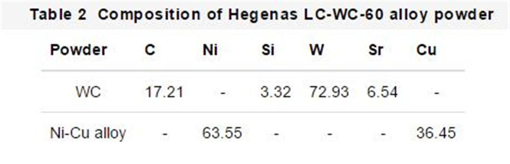
The morphology of Hegenas LC-WC-60 powder is shown in Figure 1. It can be seen that the Hegenas LC-WC-60 powder is a mixed powder of Ni-Cu alloy and WC particles, and the powder has a spherical shape, which can ensure good fluidity. The composition of Hegenas LC-WC-60 alloy powder tested by EDS is shown in Table 2.
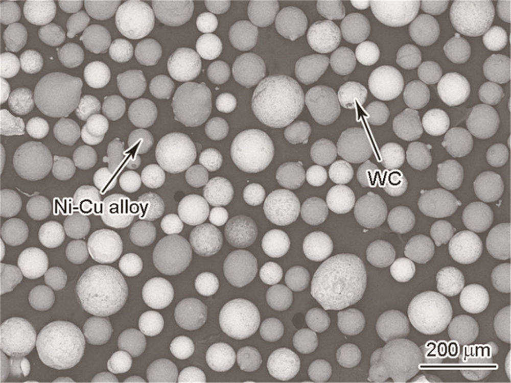
Fig.1 Backscattered electron (BSE) image of Hegenas LC-WC-60 powders
2.2 Coating surface morphology
The surface morphology and roughness of No.1 and No.2 nickel-based WC coatings are shown in Figure 2. The surface roughness (Ra) of No.1 and No.2 samples are 11.4 and 30.5 μm, respectively. This is because, under the same conditions of other process parameters, the low-speed laser cladding has a lower linear speed, more powder participates in forming within the same distance, a higher melting height, and more obvious overlap between passes. At the same time, in the low-speed laser cladding process, most of the laser energy acts on the substrate, and the powder is not fully heated and melted before reaching the molten pool. The phenomenon of powder sticking is more likely to occur during the cladding process, which increases the surface roughness of the coating. In the ultra-high-speed laser cladding process, most of the laser energy is applied to the powder, and the Ni-Cu alloy is fully heated and injected into the molten pool in liquid form. The coating surface is smoother and the roughness is lower. Therefore, the use of ultra-high-speed laser cladding can greatly reduce the amount of cutting during subsequent processing while improving efficiency.
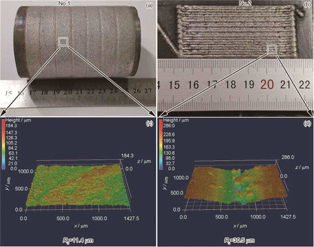
Fig.2 Surface morphologies (a, b) and roughness (Ra) (c, d) of No.1 (a, c) and No.2 (b, d) Ni-based WC coatings
2.3 Coating structure
The BSE image and the EDS analysis of the transition zone elements of No.1 and No.2 nickel-based WC coatings are shown in Figure 3. It can be seen from Figure 3a that the coating thickness of No. 1 is 280 μm, the coating is uniform and dense, without defects such as pores and cracks, and the distribution of WC particles is relatively uniform. Figure 3c shows that the coating thickness of No. 2 is 850 μm, the penetration depth and penetration width of the coating are larger, the distribution of WC particles is uneven, and there are a large number of pores of different sizes, and more carbides are precipitated. Evenly distributed WC particles are beneficial to improve the wear resistance of the coating and reduce the tendency of coating cracking. The EDS line scan of the main elements Fe, Ni, and Cu of the coating shows that the element transition zone between the coating and the 45 steel substrate in No. 1 is 5 μm (Figure 3b), while the element transition zone in No. 2 is 60 μm. (Figure 3d), which is 12 times that of the ultra-high-speed laser cladding sample (No. 1). The smaller the element transition zone, the less the matrix melts during the cladding process. This is because in low-speed laser cladding, the laser energy is more applied to the substrate, and the linear velocity is lower, and the substrate melts more, which increases the coating dilution rate. Table 3 shows the EDS surface scanning composition analysis of the sections of No.1 and No.2 nickel-based WC coatings. The scanning area of No.1 is 0.5 mm2, and the scanning area of No.2 is 0.8 mm2. Compared with No.1, the nickel-based WC coating of No.2 has the base element Fe content (mass fraction, %, the same below) in the coating increased from 1.51 to 28.31, and the W content decreased from 42.49 to 34.84. Si, Ni The mass fractions of, Cu and Sr also decreased to varying degrees, indicating that the No. 2 nickel-based WC coating was seriously diluted by the substrate.
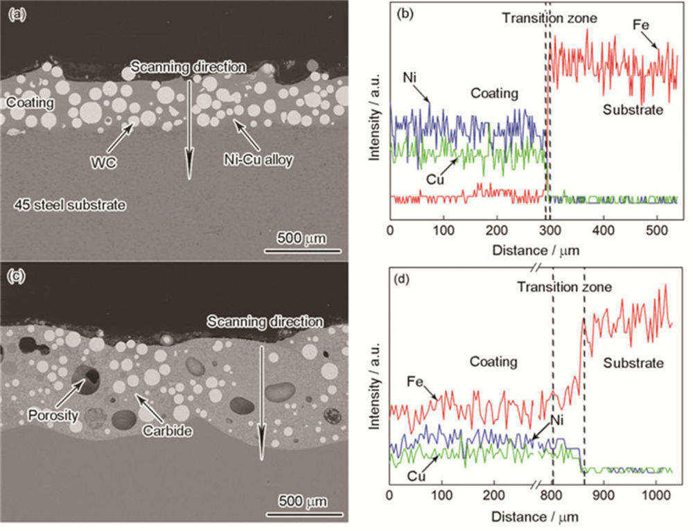
Fig.3 BSE images (a, c) and corresponding EDS analyses of elements in transition zone (b, d) of No.1 (a, b) and No.2 (c, d) Ni-based WC coatings
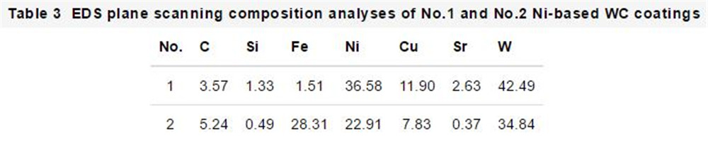
The SEM and BSE images of the microstructure of No.1 and No.2 nickel-based WC coatings are shown in Figure 4. Figures 4a and b show that in the No.1 coating, the WC particles suffered little thermal damage, no obvious carbides were observed in the coating, and the structure was composed of fine dendrites and interdendritic eutectic produced by rapid solidification. Phase composition. Figures 4c and d show that under the larger heat input of No. 2, the WC particles falling into the molten pool were severely thermally damaged, and the dissolution was obvious, and carbides with different morphologies were precipitated around the WC particles and at different positions of the coating. The EDS component analysis of different points in Figure 4 is shown in Table 4. In the No.1 coating, the dendrites (C) around the WC particles are rich in Ni and Cu, and contain C, W, and a small amount of Si; the eutectic phase (D) is rich in Ni and Cu, indicating that the WC particles have occurred Slight thermal decomposition. At the same time, the alloying element W is solid-dissolved in the dendrites, while maintaining the structural integrity of the WC, it improves the bonding strength between the WC particles and the Ni-Cu alloy, which is conducive to its wear resistance. The dendrites far away from the WC particles (A) are rich in Ni, Cu, C, and a small amount of Si; the eutectic phase (B) is rich in Ni and contains C, Cu, and a small amount of Si, neither of which contains W. It shows that the thermal decomposition of WC particles is very slight. In No.2 coating, the strip-shaped carbide (F) far away from the WC particles is rich in W, containing higher Fe, C, Ni, and a small amount of Cu. The white spherical structure is WC phase, and the surrounding flocculent carbides (G) are rich in W and C and contain higher concentrations of Ni and Cu. The farther away from the WC particles, the lower the content of W and C in the precipitated carbides, and the higher the content of Ni and Cu. The XRD spectra of No.1 and No.2 nickel-based WC coatings are shown in Figure 5. It can be seen that No. 2 has more carbides in the coating than No. 1, which indicates that the WC particles in the No. 2 coatings have undergone severe thermal decomposition.
Fig.4 Secondary electron (SE) (a, c) and BSE (b, d) images of the microstructure of No.1 (a, b) and No.2 (c, d) Ni-based WC coatings
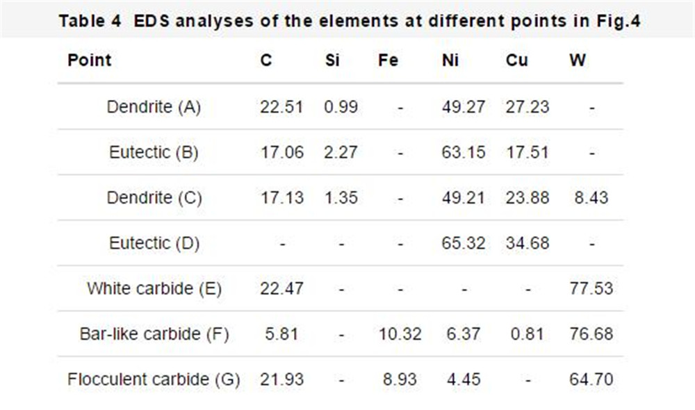
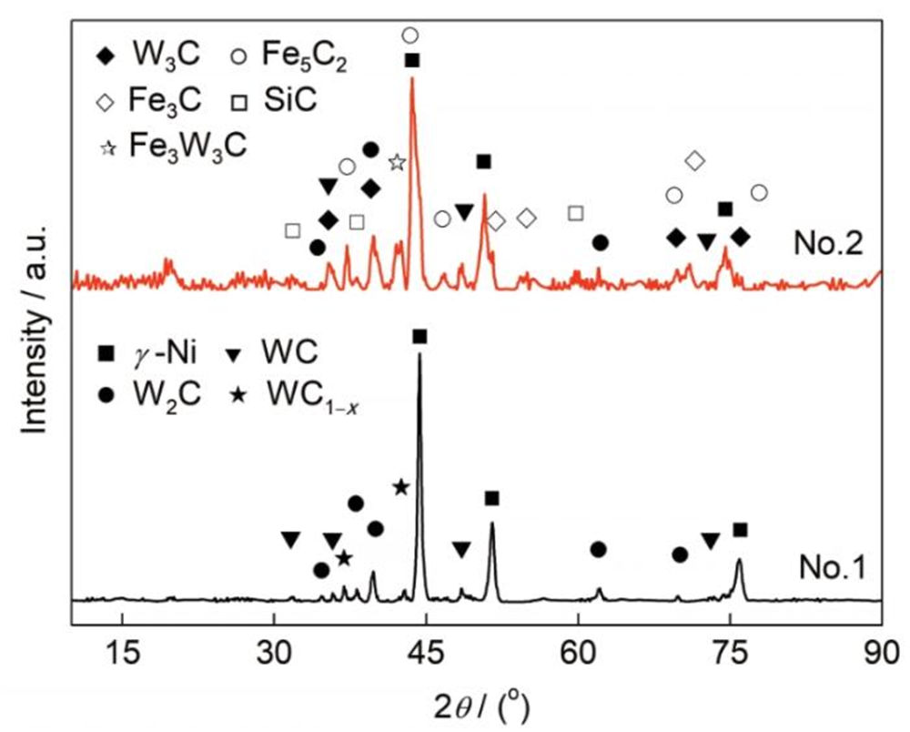
Fig.5 XRD spectra of No.1 and No.2 Ni-based WC coatings
2.4 Coating hardness and wear resistance:
The microhardness distribution of No.1 and No.2 nickel-based WC coatings is shown in Figure 6 (excluding WC particles). From left to right are the hardness distribution curves of Ni-Cu alloy, heat-affected zone and matrix in No.1 and No.2 respectively. The hardness of the Ni-Cu alloy in No. 2 coating is higher than that of No. 1. This is because the Ni-Cu alloy in No. 2 precipitates more carbides, which greatly improves the hardness. The heat-affected zone of No.2 is 180 μm, and the width of the heat-affected zone of No.1 is 60 μm. The width of the heat-affected zone of No.2 is three times that of No.1, indicating that the low-speed laser cladding has a greater heat input to the substrate.
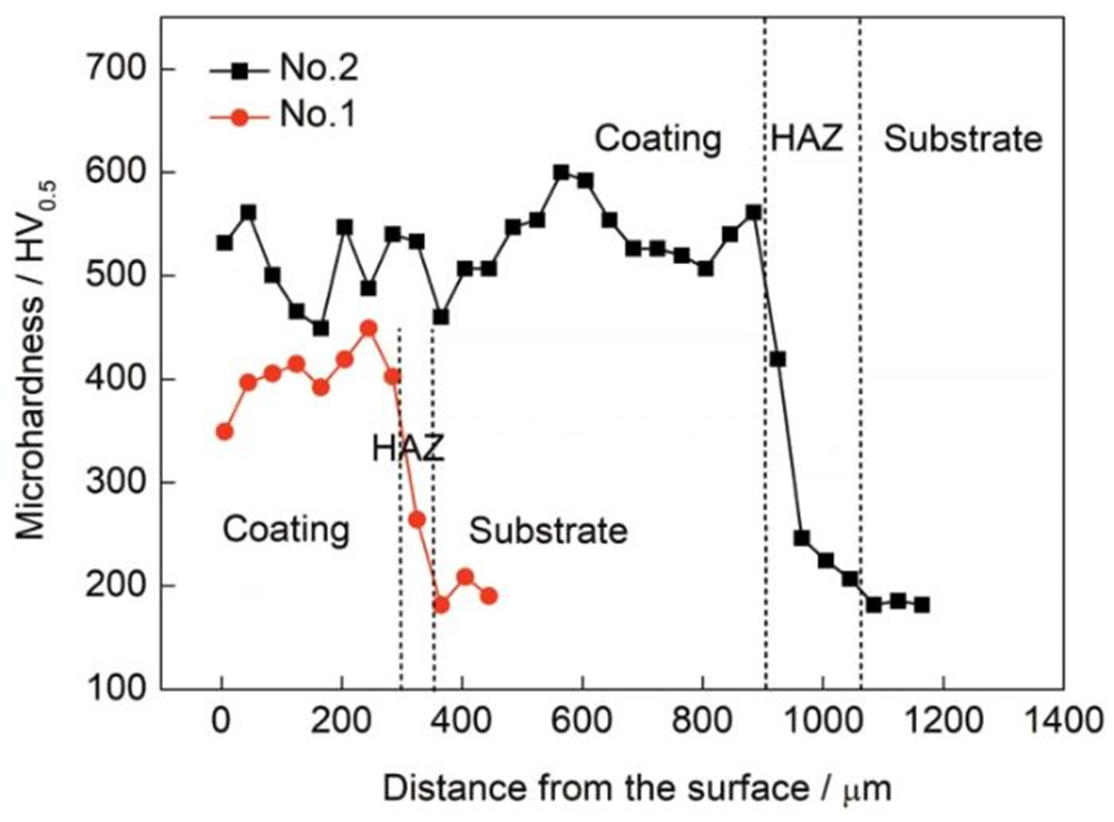
Fig.6 Microhardness distributions of No.1 and No.2 Ni-based WC coatings without WC particles (HAZ—heat affected zone)
Figure 7 shows the friction coefficient and wear loss of No.1 and No.2 nickel-based WC coatings. After 30 minutes of pin disk wear, the wear loss of the 45 steel substrate reached 127.70 mg, while No.1 was 0.68 mg, and No.2 was 1.03 mg. The wear loss weight was significantly reduced, indicating that the nickel-based WC coating prepared by laser cladding The layer can indeed greatly improve the wear resistance of the substrate. The wear loss of No.2 is 51% higher than that of No.1, indicating that the nickel-based WC coating prepared by ultra-high-speed laser cladding has better wear resistance. The hardness of WC ceramic reinforced particles is much higher than GCr15 (61~63 HRC). Therefore, in the chip wear experiment, the unevenness on the surface of the WC particles can scratch and grind the GCr15 disc, increasing the friction coefficient [21]. The friction coefficient of No.1 is 0.57, No.2 is 0.47, and the 45 steel matrix without WC particles is the lowest at 0.42. It also shows that the nickel-based WC coating prepared by ultra-high-speed laser cladding has higher WC content, more uniform distribution, and better wear resistance.
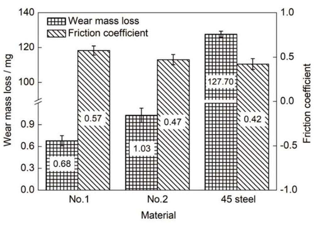
Fig.7 Friction coefficient and wear mass loss of No.1, No.2 Ni-based WC coatings and 45 steel substrate
3 Analysis and discussion:
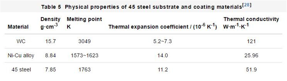
The BSE image of cracks in the No. 2 nickel-based WC coating is shown in Figure 8. Figure 8a shows the cracks around carbide/WC in No. 2 coatings. No.2 WC particles are unevenly distributed during the solidification process and carbides of different shapes are precipitated. The coefficient of thermal expansion is small in the areas where the WC particles are densely distributed, and the coefficient of thermal expansion is larger in the areas where the WC particles are sparsely distributed. From equation (4), the uneven distribution of WC particles increases the thermal stress of the coating. In addition, the precipitation of carbides on the one hand increases the microstructure stress in the coating, on the other hand, carbides of different shapes, especially rod-shaped carbides, will reduce the wettability between the alloy and the carbides and improve Crack sensitivity of the coating. Therefore, when the residual stress is greater than the strength of the coating, cracks initiate.
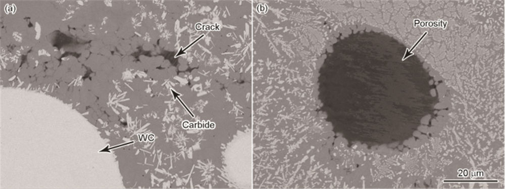
Fig.8 BSE images of cracks around carbides (a) and cracks around porosity (b) in No.2 Ni-based WC coating
Wear mechanism of nickel-based WC coating:
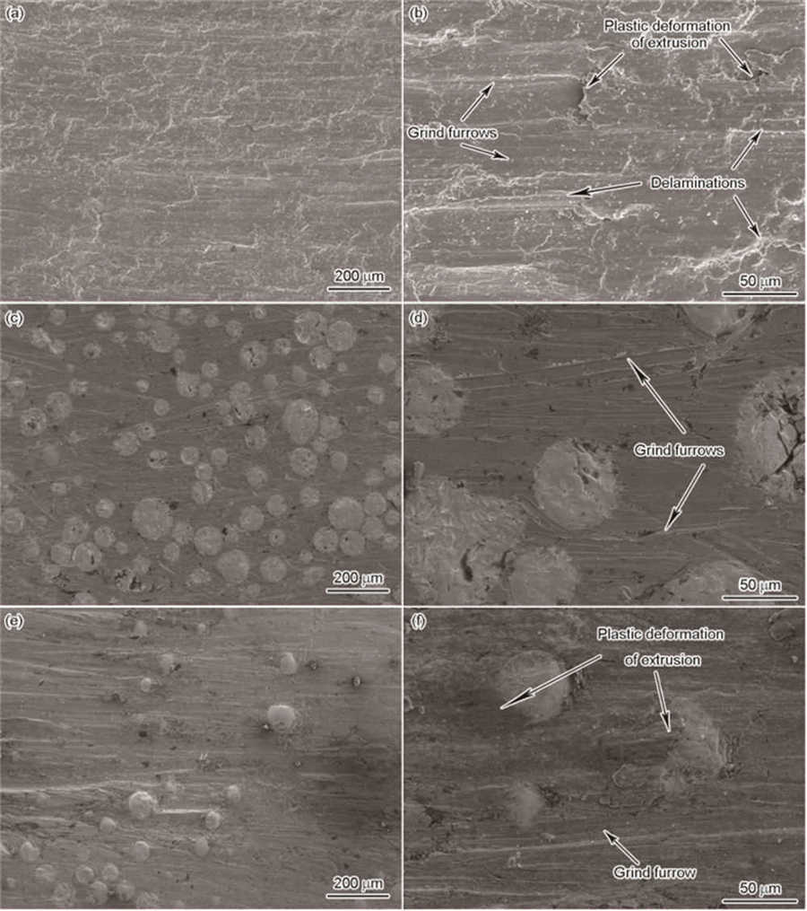
The surface wears SEM images of the 45 steel substrate are shown in Figures 9a and b. Figure 9a shows that the surface of the 45 steel abrasion specimen is relatively severely worn. It can be seen from Fig. 9b that obvious plastic deformation, micro-plowing, and delamination of the 45 steel matrix occur after wear, which is mainly caused by adhesive wear, abrasive wear, and delamination wear. The hardness of GCr15 is much higher than that of 45 steel. During the wear process, it can be pressed into the surface of the 45 steel matrix to cause plastic deformation in the contact area. As the wear process progresses, frictional heat causes local contact areas to reach high temperatures and welds certain locations together. Under the action of shear stress, this area is sheared and produces abrasive debris. Under the action of normal force, the abrasive debris cuts the surface of the material like a tool and produces furrows. During the wear process, the dislocations generated on the subsurface of the wear scar encounter obstacles, such as grain boundaries, inclusions, etc., will accumulate or form micro-cracks, and the micro-cracks will further aggregate to form continuous cracks parallel to the surface, eventually resulting in the entire 45 steel Peeling, delamination and wear appear.

click here to leave a message