Have any questions?
Get in touch-
Tel : +86 18355532477
-
Whatsapp : +8618355532477
-
Email : 247137166@qq.com
-
Skype : 247137166@qq.com
- contact


Have any questions?
Get in touchTel : +86 18355532477
Whatsapp : +8618355532477
Email : 247137166@qq.com
Skype : 247137166@qq.com

Isolator-free unidirectional thulium-doped fiber laser
Mar 25 , 2021Abstract:
We report the first demonstration of a unidirectional, isolator-free 2-μm thulium-doped fiber (TDF) laser, relying on the properties of the theta cavity (ring resonator with S-shaped feedback). The core pumped theta cavity TDF laser provides sub-Watt output power with a slope efficiency of 25%, a 2 dB flat tuning range of 1900–2050 nm, and a linewidth of 0.2 nm, and achieves the extinction ratio of 18–25 dB (depending on the feedback value) between the favored and suppressed lasing directions. It is shown that these characteristics are competitive with, if not superior to, those of conventional ring cavities. The simulation results of the linear and Kerr-nonlinear theta cavities are also presented, explaining certain unexpected features of the laser behavior and establishing the importance of the doped fiber nonlinearity on the spectral shaping of the emitted signal.
Introduction:
The wavelength region near 2 μm has gained steadily increasing interest in recent years. The development of laser sources in this spectral band, based on radiative transitions in thulium and holmium trivalent cations, Tm3+ and Ho3+, respectively, is motivated by numerous potential applications in spectroscopy, remote sensing, medicine, telecommunications, and material processing. For example, multiple absorption lines of atmospheric components, such as H2O, CO2, or NO2 are exploited in differential absorption lidar (DIAL) systems1,2,3,4. The first vibration overtone of the O–H bond in water has an absorption wavelength of 1.92–1.94 μm, which can be used for laser surgery5. The atmospheric transmission window also includes the 2-μm region, unlocking the way to energy delivery6 or free-space communications7. Recently, the potential of hollow-core photonic bandgap fibers8 combined with thulium-doped fiber (TDF) amplifiers9 for fiber optical telecommunication in the 1910–2020 nm band was reported. Furthermore, the 2-μm spectral range is also widely used to pump holmium-doped fibers10 or to drive nonlinear processes in the mid-infrared region11,12. For most of these applications, a broadly tunable narrow linewidth laser source at 2 μm is required.
Due to their many advantages, such as compact size, reliability, and high output power, fiber lasers have been used in most recent developments. All-fiber core-pumped ring cavity TDF lasers (TDFL) exploiting fiberized grating-based filter13,14 or Fabry–Pérot etalon15 as a wavelength selective element and high-power cladding pumped holmium-doped fiber lasers10 have been reported. Tunable sources based on parametric conversion and subsequent amplification in TDFs delivering more than 100 mW of continuous wave power while modulation capable were also recently demonstrated16.
For the fiber ring cavity, an optical isolator should be inserted into the cavity to ensure unidirectional lasing. The fiber isolator conventionally includes Faraday rotators and 45° cross-polarizers with adjacent free-space optics17, and therefore suppresses backward propagating light within a given bandwidth, generally not exceeding several tens of nanometer. Therefore, the isolator-free, unidirectional ring fiber cavity (sometimes referred to “theta”18 or “yin-yang”19 resonators) represents an attractive and cost-effective alternative solution. In theta cavities, non-reciprocal losses are introduced by providing an S-shaped feedback within the main ring. Ja et al.19,20,21 used the fiber theta resonator to implement passive devices, such as bandpass/bandstop filters and wavelength division multiplexers/demultiplexers. An erbium-doped fiber laser with a theta cavity providing a nearly 20 dB extinction ratio (ER) between output signals, propagating in favored and suppressed directions, was demonstrated22. This type of cavity was also used to realize highly unidirectional ring semiconductor lasers (ER of more than 20 dB)23, “quantum-dot-in-a-well” lasers (ER of 30 dB)24, and quantum cascade lasers (ER of approximately 10 dB)25.
In this paper, we report for the first time a unidirectional 2-μm TDF laser, exploiting properties of the theta cavity. We also provide the first comparison between the conventional ring cavity design and theta cavities with various feedback values. The experimental results validate the potential of TDF theta cavity lasers: they confirm that isolator-free, unidirectional TDF lasers provide narrowband emission, of which the characteristics (power, linewidth, and optical signal-to-noise ratio (OSNR)) are competitive, if not superior, with those of conventional ring cavities. Finally, we observe some unexpected behavior indicating that nonlinearity of the TDF plays an important role in shaping the theta cavity laser output.
Materials and methods:
The fundamental idea behind theta resonators is lasing direction rectification by introducing non-reciprocal cavity losses. The following model describes such behavior. Let us consider a ring resonator that consists of a lumped amplifying unit providing a power dependent gain G(P), where P is the input signal power, and two directional power couplers, whose cross-outputs are connected together to provide the S-shaped feedback (see Figure 1). The cross-coupling ratios of the couplers DC1 and DC2 are denoted as β and α, respectively. The losses in the cavity, excluding those induced by the feedback couplers, are represented by the lumped loss block, l. We define P1,n and P2,n the counterclockwise (CCW) and clockwise (CW) identical wavelength signals entering the amplifying unit at the nth round trip, respectively. Finally we consider that the amplified spontaneous emission (ASE) is negligible compared with the signal when the system reaches steady-state condition.
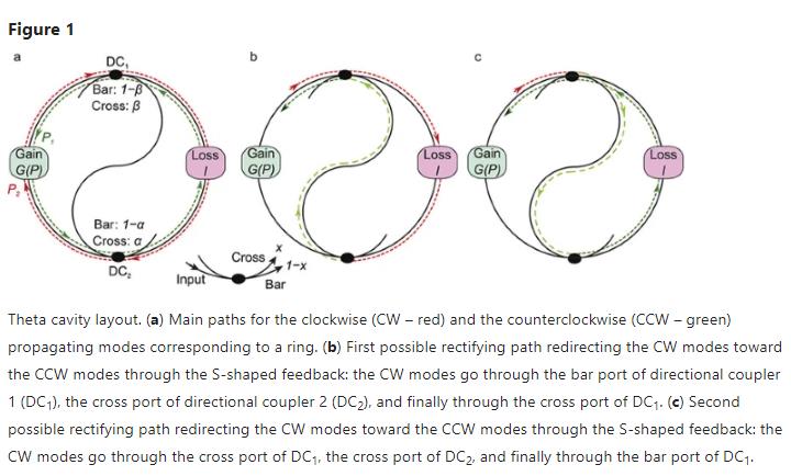
Unlike the CCW propagating signal P1,n, which simply circulates in the cavity (Figure 1a), a CW signal P2,n is partially redirected toward the CCW direction by the S-feedback, following two possible paths (Figure 1b–1c). Using the known values of the two feedback couplers, we can express, at the nth + 1 round trip, the CCW signal P1,n + 1 and the CW signal P2,n + 1 as given by Equations (1) and (2), respectively:
In Equations (1) and (2), G1 and G2 stand for the linear gain coefficients provided to the CCW and CW signals, respectively. The CCW signal has three contributions, represented by the three terms in Equation (1). The first term is the main path contribution, including the gain and loss from the cavity and couplers. The second and third terms are the contributions from the re-directed CW light through the first and second feedback paths, respectively. The CW signal only has one term, which represents the contribution from the main path. In the steady-state regime, we can write that P1,n = P1,n+1 = P1 and P2,n = P2,n+1 = P2, leading to Equation (3). We also obtain Equation (4) by substituting Equation (3) into Equation (1).
The amplifying medium at the steady-state lasing regime is typically saturated, which implies that G1 = G2, leading to P2 = 0. In other words, the CW component is completely suppressed for any coupling ratios α and β. Thus, we are able to rewrite Equation (3) as Equation (5):
where represents the total losses in the theta cavity. The condition given in Equation (5) is used to determine the steady-state gain and consequently the input CCW signal entering the gain medium in this regime. The coupling ratios α and β define the amount of redirected signal per round trip and thus affect the transient time of the cavity before reaching steady-state. Additionally, as will be described in the next section, we experimentally observed that, contrary to the prediction of this simple theory, the value of the coupling ratios influences the ER between the favored and suppressed direction. The model also excludes the Kerr nonlinearity and the backward scattering effects (Rayleigh and Brillouin scattering), which affect the performance of the real laser.
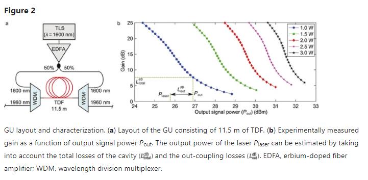
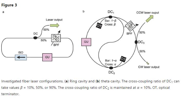
The theta fiber cavity and conventional ring fiber cavity based on the same elements were experimentally investigated to obtain the first direct comparison between both configurations. The same gain unit (GU) was used for all designs. The GU consists of 11.5 m of TDF (TmDF200, OFS Fitel Denmark ApS, Brøndby, Denmark) bidirectionally core pumped with a 1600-nm pump obtained from an amplified tunable laser source (TLS), as shown in Figure 2a. The GU was characterized with single-pass gain measurements (G) as a function of output signal power (Pout) for a 2000-nm input signal obtained from a customized TDFL. The data were obtained for five pump powers, from 1 W to 3 W, and are plotted in Figure 2b. To estimate the intra-cavity signal power emitted by the GU in the steady-state, the total losses in the cavity Ltotal are evaluated by measuring the loss of the various cavity components. The working point, given by G = Ltotal, is identified on the gain function G(Pout), and the laser output power is calculated as Plaser = Pout − Lout, where Lout is the out-coupling losses (see Figure 2b). The losses for the four cavities considered are summarized in Table 1. A standard ring cavity and the theta cavity with three different feedback values are studied (Figure 3). In addition to the GU, the ring cavity includes an optical isolator (ISO), a manually tunable, grating-based bandpass filter (BPF; full-width half-maximum (FWHM) of 2 nm), and a 50% output directional coupler (DC). The theta cavity layout replicates the ring with the exception of the two additional couplers used to replace the isolator to introduce non-reciprocal properties, as shown in Figure 3b. Three configurations are investigated by changing the coupling ratio of DC1: cross-coupling of β = 0.1 for configuration Theta1 (i.e., weak feedback), β = 0.5 for configuration Theta2, and β = 0.9 for configuration Theta3 (i.e., strong feedback). The cross-coupling ratio for DC2 is held constant at α = 0.1 for all configurations. Additionally, to prevent any possible parasitic reflections in the cavity, the unconnected ports of DC1 and DC2 are terminated (optical terminator). Because there were no polarizers inserted in the cavities, the laser emission was assumed to be depolarized, and polarization controllers were not included.
The cavity losses are higher for the theta cavities due to the inclusion of two additional couplers compared with a single isolator. The cavity losses increase as the feedback gets stronger, such that Theta3 has an 8.2 dB higher cavity loss compared with the standard ring cavity. Such higher losses affect the transient time of the cavity before reaching steady-state. The four lasers were assembled and characterized in terms of output power, OSNR and linewidth, both as a function of laser output wavelength and pump power.
Results and discussion:
First, the output power was measured as a function of wavelength (Figure 4a). For the theta cavities, the results for both the favored direction (CCW in our case) and suppressed direction (CW) are presented, and the ER between the two is plotted in Figure 4c. Contrary to the prediction from the simple theory previously presented, the suppressed direction is not perfectly eliminated, and the ER changes with the feedback coupling value. As the feedback gets stronger, the CW direction is more efficiently suppressed: an ER in excess of 22 dB is measured for Theta3, whereas Theta1 has an average ER of 18 dB. Despite these differences, the lasing direction rectification by the introduction of non-reciprocal cavity losses is indeed achieved for different values of feedback. The ER values are in a good agreement with those reported for a theta cavity erbium-doped fiber laser22. Stable lasing in the range of 1900–2050 nm is obtained with the isolator-free cavities. For the 2 W pump, output lasing power in excess of 440 mW is measured for all configurations, with a remarkable 2 dB output flatness, the isolator-free architectures thus show identical performance to the ring cavity in that regard.
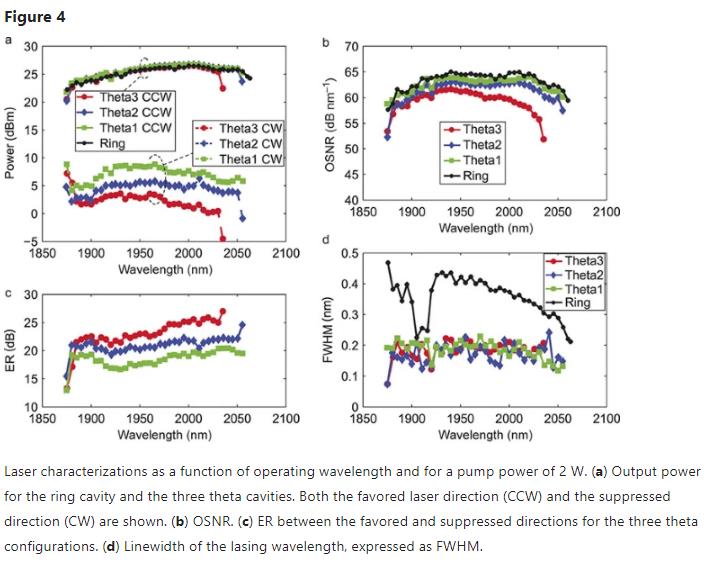
The OSNR for the four lasers, shown in Figure 4b, is better than 55 dB nm−1 over the entire 1900–2050 nm lasing range, confirming the negligible ASE once the system reaches steady-state. A maximum OSNR close to 62 dB/63 dB between 1950 nm and 2020 nm is obtained for Theta2/Theta1. The overall smaller OSNR of Theta3 is attributed to the higher total cavity losses (see Table 1) compared with the other configurations, for which the GU has to compensate.
An interesting measure is the linewidth of the lasing light. Because the laser line shape cannot be properly fitted with either Gaussian or Lorentzian functions, the FWHM is determined by , where σλ is the standard deviation of the spectral line profiles in the wavelength domain λ. The spectral line shapes of the four lasers, experimentally obtained for the wavelength of 2000 nm, are plotted in Figure 5a. Not only does the shape differ, but the values are significantly different as well. The table in Figure 5a summarizes the observed FWHM values and indicates the measured wavelength jitter. The procedure for measuring the wavelength jitter is depicted in Figure 5b: a two-dimensional histogram h(λ, P) is acquired to evaluate Δσλ. The cross section at the −3 dB point, h(λ, −3 dB) generally displays two peaks, for which the standard deviations ΔσL and ΔσU are calculated. The overall jitter is then determined as . We observed that the jitter of the theta cavity laser line at the −3 dB level is higher (30–90 pm) than that of the standard ring resonator (6 pm). This might be indicative of a continuous alteration of the longitudinal mode set within the filter bandwidth. This effect is strongly pronounced in the case of the Theta2 configuration. The averaged trace clearly possesses two peaks and demonstrates switching between two sets of modes anchored around 2000 ± 0.1 nm. The dynamic can be explained using the following qualitative model: because the re-direction of the CW propagating modes in the theta cavities via S-feedback is required, the transient time before reaching steady-state, as described in Equation 3, can be significantly longer than for a cavity with an isolator. If any environmental fluctuations within this time scale change the mode competition conditions, the transient state in the cavity with another longitudinal mode set could once again be triggered, leading to increasing jitter. During the experiments, no provisions were taken to control the operating conditions of the laser. We therefore believe that within a more controlled environment (polarization-maintained fibers, temperature stabilization), the jitter could be significantly reduced.
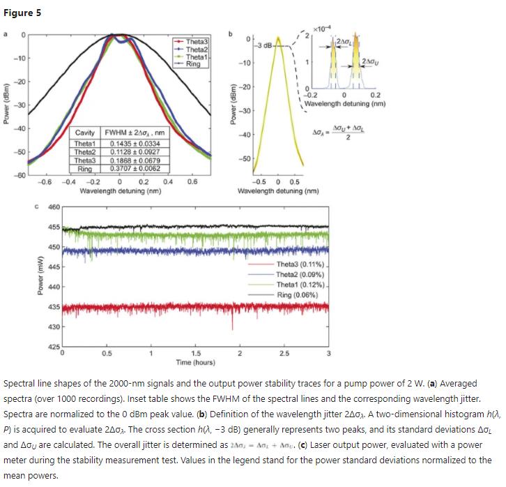
Additionally, several peaks in the laser line (similar to the Theta2-emitted spectrum) can be formed by the stimulated Brillouin scattering (SBS), which is amplified in the doped fiber. The SBS effect in the theta cavity has been already observed and exploited to build the multiple wavelength EDFL26.
The narrower linewidth for all theta cavities is consistent over the entire wavelength lasing range, as shown in Figure 4d. Quantitatively, the laser linewidth is 1.5 to 2 times narrower for the theta resonators, with an average value of 0.2 nm. We also observe that the linewidth remains constant throughout the lasing wavelength region, whereas the ring cavity exhibits stronger wavelength dependence with values between 0.2 nm and 0.45 nm.
The power of the emitted signals is kept virtually fixed in the stability tests. Its standard deviation normalized to the mean value does not exceed 0.15% for 3 hours (Figure 5c).
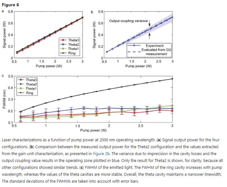
Finally, both the output power and linewidth of the 2-μm signal as a function of pump power are measured, and the results are shown in Figure 6a–6b and Figure 6c, respectively. All four lasers show almost identical results with a pump power threshold of approximately 0.2 W (not shown in the figure) and a slope efficiency in the vicinity of 25%. An output power close to 700 mW can thus be obtained when pumping with 3 W. This slope efficiency is close to the 26% value reported for a conventional all-fiber ring TDFL27. The experimental data for the output power are compared with the evaluated values using the measurements of the GU (Figure 2b) and losses (Table 1). For readability, only the result for Theta2 is shown in Figure 6b because all lasers showed a similar trend. Overall, good agreement is reached. The measured powers fall on the upper limit of the operating zone because the setup was fully optimized to reach the highest output powers. Finally, in our opinion, the most remarkable feature of the theta cavity can be observed in Figure 6c. Contrary to the ring cavity, which exhibits an increased laser linewidth with pumping power, the linewidth of the theta cavities’ lasing wavelength remains mostly constant.
To gain further understanding of the thulium-doped theta cavity laser, we performed simulations with this configuration. The simulation platform allows us to include the Kerr nonlinearity of the gain medium, an important parameter that is omitted in the simplified analytical description. We have previously observed moderate four-wave mixing (FWM) in a 4-m-long TDF as a complementary phenomenon during a multi-wavelength signal amplification in the 2 μm spectral region16. Given the relatively small TDF core size of approximately 4 μm in diameter and the high refractive index contrast (numerical aperture NA = 0.26), the presence of FWM confirms the non-negligible nonlinear coefficient γ of the thulium fiber. The impact of γ on the performance of ring/theta cavity lasers is therefore investigated numerically by implementing the experimental configurations shown in Figure 3 using VPItransmissionMaker software (VPI). The TDF model, implemented in VPI, is based on solving the coupled rate equations for the population inversions of the energy levels and the propagation equations for the signals and ASE components28,29,30,31. Only the effect of self-phase modulation (SPM) is included in the model. Relying on the initial estimations of FWM, a coefficient γ = 11.4 W−1 km−1 is assigned to the nonlinear TDF.
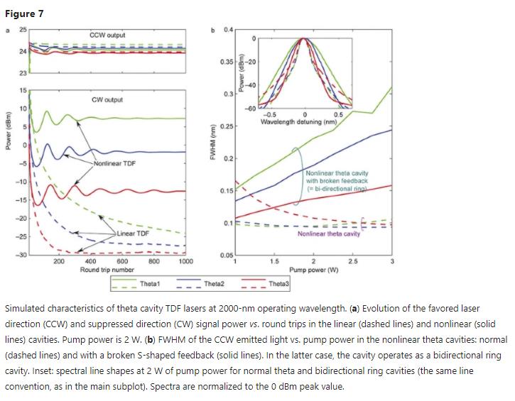
A summary of the simulation results is presented in Figure 7.
The absorption and emission cross sections and the radiative lifetime of the transition are taken from the reference (fiber Tm1)32. To perform the simulations in a reasonable computational time, the doping concentration is set to 3 × 1025 m−3 (compared with the 8.4 × 1025 m−3 reported)32, which results in a reduced gain in TDF, and therefore leads to the difference between the experimentally measured and simulated laser output powers (26 dBm and 24 dBm at 2000 nm for a 2 W pump, respectively).
The first significant discrepancy between the analytical description and experiments is the finite ER between the favored and suppressed directions. In Figure 7a, the favored (CCW) and suppressed (CW) output powers are plotted as a function of the cavity round trip for the three theta cavity configurations. The results for a linear TDF (solid line) and nonlinear TDF (dashed line) are compared. The simulation results in the linear case are in good agreement with the analytical description: (i) the power of the CW signal diminishes with every round trip (note that an apparent saturation around −30 dBm is caused by the numerical limitations of the model) and (ii) the Theta1 configuration takes longer to settle into steady-state due to the low value of feedback. When the nonlinearities are taken into account, behavior similar to the experimentally observed behavior is depicted: the CW power does not vanish in the steady-state. Some oscillations occur until a finite value is reached. The simulations predict ERs of 16.9 dB, 26.0 dB, and 36.5 dB for Theta1, Theta2, and Theta3, respectively. Qualitatively, they are in good agreement with the experiment: higher feedback provides better ER. The quantitative difference between simulated and experimental values can be attributed to the parameter discrepancies between the real and modeled TDF (primarily, the doping concentration).
The other unexpected trend is the emitted light linewidth. The simulation results for linewidth as a function of pump power are shown in Figure 7b. When nonlinearities are included in the model, the linewidth of the lasing light follows the experimental behavior: the FWHM remains virtually constant or even decreases with increasing pump power. This can be explained by the impact of the nonlinear amplifying mirror (NALM) in the cavity33. A NALM is included in the laser configuration, starting at the coupler DC2 and including the TDF and DC1. The redirected CW signal and the CCW light in the main ring acquire different nonlinear phase shifts while propagating in the TDF and interfere at DC2, resulting in the linewidth narrowing. The reverse trend (i.e., increasing linewidth with pump power) when the S-shaped feedback is broken supports this assumption. In the latter case, the laser configuration simply represents a bidirectional, nonlinear ring cavity, where the emitted signal acquires additional SPM, leading to the spectral broadening of the laser line. Moreover, similar behavior was experimentally observed in the conventional unidirectional ring cavity, where the FWHM is increased from 0.2 nm at 0.6 W of pump power to 0.48 nm at 3 W (Figure 6c).
Conclusions:
In summary, we have experimentally demonstrated the first unidirectional, isolator-free, 2-μm, TDF laser relying on the properties of the theta cavity, and provided the first comparison between the conventional ring cavity design and theta cavities with various feedback values (coupler DC1). The core pumped theta cavity TDF laser provides sub-Watt output power with a slope efficiency of 25%, a 2-dB flat tuning range of 1900–2050 nm, an OSNR of more than 60 dB, and a linewidth of 0.2 nm, and achieves an ER of 18–25 dB (depending on the feedback value) between the favored and suppressed lasing directions. These characteristics are competitive with those of ring cavities. The only theta cavity benchmark that yields to the conventional ring configuration is the temporal stability of central wavelength and FWHM, estimated by the value of wavelength jitter 2Δσλ. We believe that, within a more controlled experimental environment (polarization-maintained fibers, temperature stabilization), the jitter (30–60 pm) could be significantly reduced. Additionally, reducing the bandwidth of the bandpass optical filter should increase the stability.
Moreover, the linewidth of the theta cavities’ lasing wavelength remains mostly constant with the pumping power (FWHM of approximately 0.2 nm), whereas the emitted spectrum of the ring cavity experiences considerable broadening (FWHM increases from 0.2 nm at 0.6 W of pump power to 0.48 nm at 3 W). The simulation results show that this behavior can be attributed to the effect of the NALM in the cavity. Apart from the engineering advantage of the theta configuration, where such relatively complex and narrowband optical components, such as the optical isolator, can be omitted, the NALM impact on the spectral shaping of the emitted light represents, in our opinion, the most remarkable feature of the investigated cavity. Therefore, there is room for future investigations to optimize the interaction between NALM and the main fiber ring, improving the stability and non-reciprocity (ER) in the cavity. Moreover, because the NALM can act as an artificial saturable absorber, it could be possible to change the operating regime of the laser from continuous wave to pulsed by enhancing the nonlinear effects in the cavity with sections of highly nonlinear fibers or additional TDF pieces.

click here to leave a message