Have any questions?
Get in touch-
Tel : +86 18355532477
-
Whatsapp : +8618355532477
-
Email : 247137166@qq.com
-
Skype : 247137166@qq.com
- contact


Have any questions?
Get in touchTel : +86 18355532477
Whatsapp : +8618355532477
Email : 247137166@qq.com
Skype : 247137166@qq.com
The dynamic process of cladding forming under the combined heat source of laser and TIG arc
Apr 12 , 2021WILA uses 304 stainless steel as the base material, and conducts Ni60 powder cladding experiments with a semiconductor laser and TIG arc composite heat source on it, and uses a high-speed camera to record the dynamic change of powder melting. The changes brought about by the introduction of TIG arc are analyzed from the three aspects of force, heat and cladding layer formation. The dynamic process of powder forming under the laser arc composite heat source is described, and the force and heat conduction forms at each stage are described. The influence of TIG current on forming and forming process is explained, and the advantages of semiconductor laser and TIG composite heat source for cladding are explained.
1. The changes brought by TIG arc to the cladding layer forming and forming dynamic process
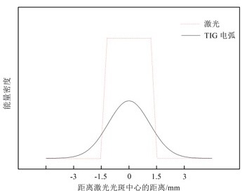
In the long-term practice, WILA has found the shortcomings of only using laser as the cladding heat source. Therefore, it is conceived to add a completely different heat source to combine the two heat sources as the cladding heat source, such as TIG arc. There is mutual influence when the two heat sources of TIG arc and laser are combined. The metal vapor generated when the laser is irradiated on the surface of the part rapidly ionizes to form charged particles, which increases the electrical conductivity at the location where the laser is applied, reduces the resistance of the arc through the path, and increases the current density of the arc. In addition, the laser changes the heat source characteristics of the arc, sharply increases the temperature of the arc center, forming a great temperature gradient between the center of the arc and the surroundings, and the arc shrinks as shown in Figure 4.1. The laser can also greatly reduce the ignition voltage of the arc, make its fluctuation smaller, and then achieve the effect of stabilizing the arc [. In addition, the heating effect of the laser on the metal surface increases the temperature, which can increase the metal's absorption rate of laser energy.
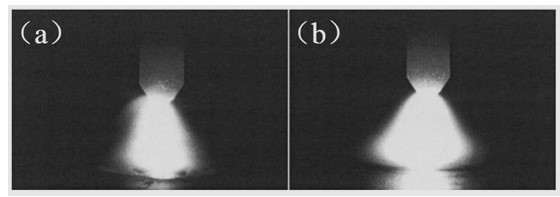
Figure 4.1 The contraction effect of the laser on the arc
(A) Combination arc shape of 500W laser and 100ATIG arc; (b) 100A TIG arc shape
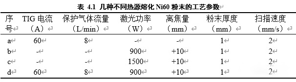
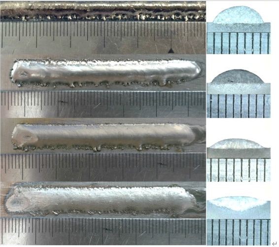
WILA has found through a large number of experiments that the introduction of TIG arc can cooperate with lower laser power to achieve a good spreading effect of the cladding layer, and obtain a cladding layer with a small contact angle and a low dilution rate. The 4 single-pass cladding layers welded according to the process parameters shown in Table 4.1, and the cladding layer shape and cross-sectional morphology are shown in Figure 4.2
Figure 4.2(a) is obtained by cladding with a TIG arc with a current of 60A as the heat source. It can be seen that the entire weld bead is discontinuous and the shape is extremely poor. This is because when a single TIG arc does not have laser recombination, the arc coverage area is larger, the energy is not concentrated, and the energy is relatively low when the current is small, and it cannot melt the metal powder well. Only a small amount of powder can melt and combine. Combine with the substrate. In addition, the arc force caused by the insufficiently concentrated and stable arc not only does not flatten the liquid melt to promote its spreading, but blows away the liquid pellets generated during the melting process, and finally forms a single-pass weld with discontinuous formation. Therefore, a single TIG arc is not suitable for use as a cladding heat source.
The single-pass cladding layer obtained by cladding Ni60 powder with a 900W semiconductor laser as a single cladding heat source is shown in Figure 4.2(b). It can be seen that although the cladding layer is well combined with the substrate, the entire cladding layer is tall, the contact angle is large, and the edge shape is poor, indicating that the cladding layer is poorly spread, which will seriously affect the smooth subsequent lap in the multi-pass cladding. get on.
Usually the surface tension of the liquid is inversely proportional to the temperature, so if the temperature increases, the surface tension of the liquid decreases, which will improve the wetting and spreading. Therefore, when the laser power is increased to 1500W, the temperature of the liquid melt increases significantly, which greatly reduces the surface tension. Moreover, due to the extremely high laser power, the amount of powder melted is also large, and the gravity of the liquid melt is large enough to easily overcome the surface tension and spread the liquid melt, and finally form a cladding layer with good spreading and small contact angle.
The single-pass cladding layer obtained by cladding Ni60 powder with a 1500W semiconductor laser as a single cladding heat source is shown in Figure 4.2(c). It can be seen that under high laser power, the cladding layer spreads well and the contact angle is small, but the matrix area has a larger penetration depth and the dilution rate is higher. There is a problem that the alloy composition of the cladding layer is diluted by the matrix. In addition, many cracks perpendicular to the scanning direction can also be clearly observed from the surface of the cladding layer, which are caused by the higher temperature gradient and larger residual stress brought by the high laser power.
The cladding layer obtained by the composite cladding of 900W laser and 60A TIG arc is shown in Figure 4.2(d). It can be clearly seen that the cladding layer spreads well and the contact angle is small, which is significantly better than 900W laser cladding The obtained cladding layer has a better forming effect than the cladding layer obtained by 1500W laser cladding, and the penetration depth is not large, and the dilution rate is low, which is an ideal cladding layer forming. Carefully observe the surface of the cladding layer, and no obvious cracks were found. This is because firstly the addition of the TIG arc increases the heat input and reduces the surface tension of the liquid melt, and the unique energy distribution formed by the combination of the two heat sources is conducive to reducing the residual stress and reducing the occurrence of cracks. In addition, the TIG current brings extra force to the melting and spreading process, and under the action of the laser, the arc shrinks and stabilizes, and the force becomes concentrated, which promotes the melting and spreading process. Under the combined action of the above two factors, a more ideal cladding layer formation is formed.
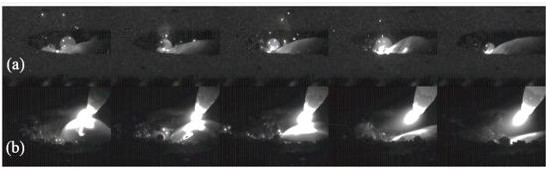
In order to be able to clearly observe the difference between the cladding forming process under a single laser heat source and a composite heat source, the high-speed camera is arranged perpendicular to the scanning direction, and the angle between the camera and the horizontal plane is as small as possible to observe the changes in spreading. Take pictures of the cladding area, and cut out frames with key features for sorting. Figure 4.3 is a high-speed camera comparison of 900W laser heat source and 900W laser and 60A TIG arc composite heat source cladding. It can be seen that the process of powder melting and spreading under a single laser heat source and a composite heat source is quite different. With a single laser heat source, the powder is first melted into some small balls under the irradiation of the laser, and then these small balls contact and fuse and grow up, and new molten balls are continuously melted into them from the side to form a large liquid melt. . At a certain scanning speed, the front end of the liquid melt continuously melts and extends forward, and the back end solidifies, finally forming a complete single-pass cladding layer. From the high-speed camera screenshots, there is no obvious change in the spreading of the whole process, as shown in Figure 4.3(a). Under the action of the composite heat source, the laser melts the powder at the front to form a liquid melt, and the arc quickly flattens the liquid melt at the back to spread it. And it can be clearly seen from the high-speed camera screenshots that there is a transition from poor spreading to excellent spreading in the cladding process under the composite heat source, as shown in Figure 4.3(b).
2. Force analysis of liquid melt under the action of TIG arc
According to the electromagnetic shrinkage effect, when the current flows through a conductor, it can be regarded as composed of many parallel current lines. These parallel current lines will attract each other to make the cross-section tend to shrink. The resulting force is called electromagnetic shrinkage. Force [50]. TIG arc is a conical gaseous conductor with variable cross-section diameter. The arc cross-section diameter is small near the tip of the tungsten electrode, and the arc cross-section diameter is larger near the workpiece end. The difference in the diameter of the upper and lower cross-sections causes the pressure difference, which will produce the axial component of the electromagnetic contraction force from the tip of the tungsten pole to the workpiece, which is the electromagnetic static pressure. Also, the TIG arc introduces plasma flow force and shielding gas blowing force for the entire dynamic process. The above three forces can promote the movement and convergence process of the liquid pellets and agitate the molten pool to promote flow, which improves the spread of the liquid melt. The overall force diagram is shown in Figure 4.4.
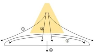
Figure 4.4 Schematic diagram of force analysis of liquid melt under the action of TIG arc
1. Plasma flow force and shielding gas blowing force; 2. Electromagnetic static pressure; 3. The flow of liquid melt on the surface; 4. Gravity
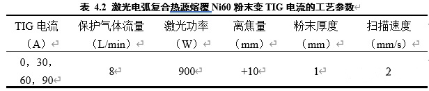
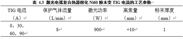
According to the parameters in Table 4.2, a single-pass cladding Ni60 powder test was performed on a 304 stainless steel substrate with a semiconductor laser and a TIG composite heat source. The obtained cladding layer and its corresponding cross-section are shown in Figure 4.6.
It can be seen from Figure 4.6 that the width of the cladding layer obtained under the laser arc composite heat source is significantly higher than that of the cladding layer obtained under a single laser heat source. Another obvious feature is that the surface of the cladding layer obtained by the composite heat source cladding is relatively flat, unlike the cladding layer obtained by a single laser heat source that is taller than the substrate. and. As the TIG current increases from 30A to 60A, the surface forming of the cladding layer has become significantly smoother, but the penetration depth and dilution rate of the cladding layer have increased. This is because the higher TIG current brings greater arc force, which constantly agitates the molten pool, further flattens the liquid melt, but also increases the penetration depth, melting more base metal, and affecting the cladding layer. The ingredients cause dilution. When the TIG current rises to 90A, it can be seen that the penetration depth is very large. At this time, the cladding layer is greatly diluted by the substrate, which seriously affects the performance of the cladding layer. Moreover, when the TIG current is too large because the preset powder cladding process often produces splashes, the high-temperature tungsten is very easy to adhere to the molten pool and causes short-circuit arc extinguishing, so it is necessary to avoid using excessive TIG current in the composite cladding.
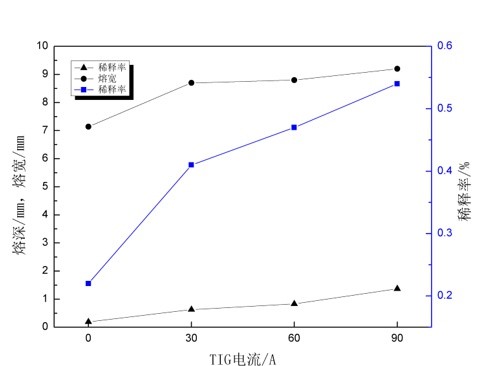
The measurement and analysis of the cross-section of the cladding layer can calculate and plot the influence of the TIG current on the penetration depth, penetration width, and dilution rate in the composite heat source cladding, as shown in Figure 4.7. It can be seen that with the increase of the TIG current in the composite heat source cladding, the penetration depth and dilution rate of the cladding layer both show an increasing trend, while the degree of change in the melting width is not large. Compared with the composite heat source, because the energy of a single laser heat source is concentrated in the spot area, the heat-affected zone is small, so the melting width is small, and because the heat input is not large, the penetration and dilution rate are also small. After the introduction of the TIG arc, the heating range of the arc and the heat-affected zone are larger than that of the laser, and the energy is not as concentrated as a single laser heat source, so the melting width is significantly increased, which will help improve the cladding efficiency. Besides, compared with a single laser heat source, the addition of the TIG arc increases the overall heat input of the composite heat source, so the penetration and dilution rate is also greatly improved. Regarding the higher TIG current in the composite heat source, although the spreading of the liquid melt is improved and the contact angle is reduced, it also brings about the problem that the cladding layer metal is diluted by the low-performance matrix component, and the dilution rate is higher.
According to the process parameters shown in Table 4.1, test and extract the characteristic behaviors in the forming process from the high-speed camera videos, record the number of frames of each characteristic behavior, and calculate and analyze the TIG current to the composite heat source forming stages. The impact is shown in Figure 4.8.
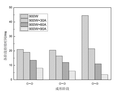
It can be seen from Figure 4.8 that compared to a single laser heat source that takes a lot of time in stages ③~④, there is no such problem in the cladding of a composite heat source. And with the increase of TIG current, the time of stage ①~②, stage ②~③, and stage ③~④ will be shortened. This is because the TIG arc is the convergence and fusion of the liquid pellets, and the spreading of the liquid melt provides the additional force. And these additional forces are proportional to the TIG current, so as the TIG current increases, the electromagnetic static pressure, plasma flow force, and shielding gas blowing force acting on the liquid metal will increase, speeding up the various stages of the forming process. The completion.
When the spread of the liquid melt tends to be stable and the contact angle remains basically unchanged, the fta32 software is used to measure the contact angle at this time. Perform 5 tests for each parameter and record the contact angle separately to get the influence of the TIG current on the contact angle in the composite heat source cladding, as shown in Figure 4.9.
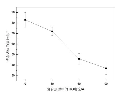
It can be seen from the above analysis that the introduction of the TIG arc provides the additional driving force for the convergence and spreading of the liquid melt during the forming process, and it increases the temperature of the liquid melt and reduces its surface tension, which significantly speeds up the dynamic process. Under the constraint of scanning speed, the liquid melt can be spread in time to form a cladding layer with good spreading and a small contact angle. And it avoids problems such as high dilution rate, high residual stress, and easy cracking caused by excessive heat input. The laser and TIG arc composite heat source is a cladding heat source with obvious advantages. It not only solves the forming and performance problems, improves the cladding efficiency, but also reduces the dependence on high-power lasers and reduces equipment costs.

click here to leave a message